

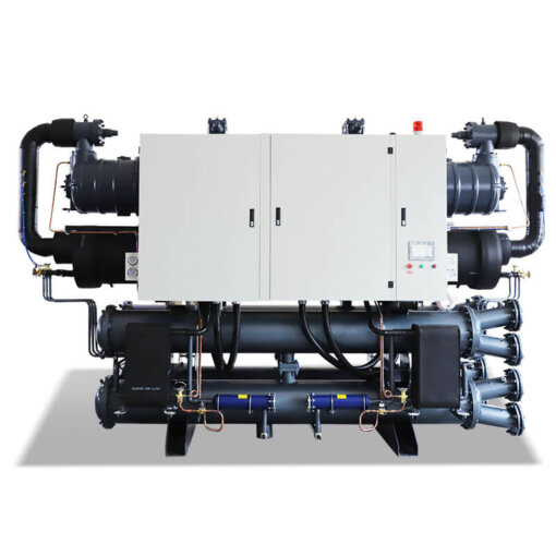

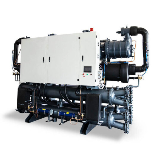
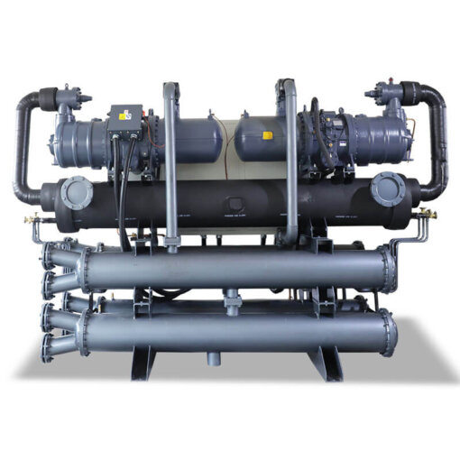
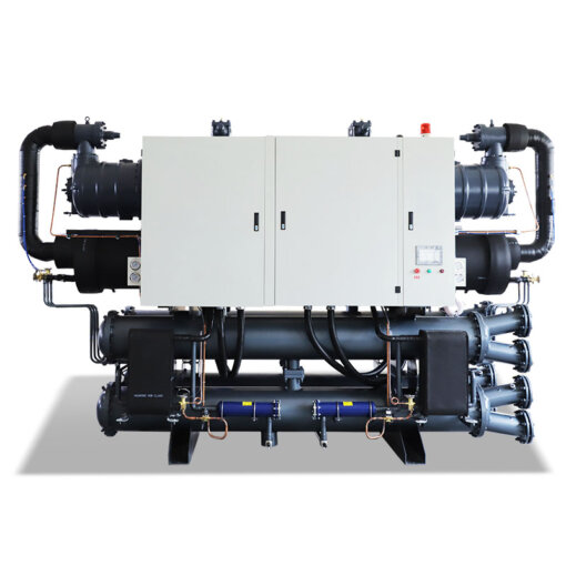
Total heat recovery unit
The total heat recovery unit is suitable for use in processes that require both chilled water and hot water. When the unit produces cold water, it simultaneously recovers heat to produce hot water. The cold water produced is used for the cooling processes in the production process, and the hot water produced is used for the heating processes in the production process. This unit is widely used in special industries that require both cooling and heating supply.
The full heat and full cold recovery unit adopts internationally renowned brand screw compressors, and is equipped with high-quality and high-efficiency copper tubes to make condensers, evaporators and world-class control components. This makes the unit feature small size, low noise, high energy, long service life and easy operation. Its elegant and exquisite appearance design and reliable and stable high-efficiency quality stand out among similar products!
Features
1) The compressor adopts an international brand, a new type of high-efficiency screw rotor compressor, which is 20% to 30% more efficient than ordinary compressors and has obtained patents in many countries in Europe and America as well as ISO9001 international quality certification.
2) High-efficiency control of 5:6 patented asymmetric rotor tooth profile.
3) Capacity control can adopt a four-stage (-75% - 50% - 25%) or three-stage (100-66% - 33%) and stepless control system.
4) It adopts high-efficiency silicon steel and a special channel design, and is equipped with an internal and external omnidirectional cooling channel design, enabling the compressor motor to achieve higher efficiency under any load.
5) The unique built-in hydraulic system ensures that the compressor maintains better lubrication without the need for an oil pump.
6) The oil separator adopts a double-layer filtration method, which has an excellent oil filtration effect and enables the heat exchanger to exert greater capacity.
7) High efficiency, low noise and low vibration.
8) The control system of the unit adopts imported German Siemens PLC program controller, and the human-machine interface is equipped with a large LCD touch screen to achieve intelligent human-machine dialogue.
9) The system is equipped with functions such as motor overload protection, short circuit protection, overheat protection, high voltage protection, low voltage protection, compressor delayed start protection, and water flow protection, ensuring the safe and reliable operation of the unit.
10) The system integrates the interlocking control of external operating components as a whole, facilitating the stable and efficient operation of the system, reducing the installation volume for customers and the repetitive production of control systems
The application scope of the unit
The total heat recovery unit models are mainly divided into the following four usage scenarios.
The type is the unit that uses a chilled water temperature above 7℃ and a hot water temperature below 60℃.
The second type is units that use chilled water with a temperature above 7℃ and hot water with a temperature between 60℃ and 80℃.
The third type is the units that use chilled water temperatures below 7℃ to above 10℃ and hot water temperatures below 60 ℃.
The fourth type refers to units that use chilled water temperatures ranging from 7℃ to 10℃ and hot water temperatures ranging from 60 ℃ to 80℃.
All the usage scenarios within the above-mentioned scope range can be met. However, the corresponding models must not exceed their usage scope. The main reason is determined by the application scope of the compressor and the configuration adjustment of the system.
Process description of the unit
The process of the full heat and full cold recovery unit is divided into the chilled water process, the hot water process and the cooling water process.
1) The chilled water flow of the full heat and full cold recovery unit
The chilled water process of the total heat recovery unit is as follows: The chilled water pump draws the water from the chilled water tank and sends it to the evaporator of the unit. The evaporator freezes the incoming water, and the low-temperature chilled water then enters the equipment that needs to be chilled.
However, considering that the circulation volume of chilled water required by the evaporator of the unit will be greater than the flow rate of the equipment in use, the chilled water completed from the evaporator is divided into two paths. One path enters the equipment in use that needs to be chilled, and the other path enters the chilled water tank. The chilled water entering the chilled water tank is to ensure the normal flow rate of the equipment in use, so it needs to be regulated. That is, a regulating valve should be installed on the pipeline where the chilled water coming out of the evaporator of the unit enters the water tank.
The chilled water entering the equipment to be used cools it down and then flows back to the chilled water tank. The water entering the chilled water tank mixes with the water bypass to the chilled water tank and is sent to the evaporator of the refrigeration unit by the chilled water pump for the next refrigeration cycle.
2) The hot water flow of the full heat and full cold recovery unit
The hot water process of the full heat recovery unit is as follows: The hot water pump draws the water from the hot water tank and sends it to the heat recovery device of the refrigeration unit. The water entering is heated by the heat recovery device, and the high-temperature water after heating enters the equipment that needs to be heated.
However, considering that the circulation volume of hot water required for the normal operation of the unit will be greater than the flow rate of the equipment in use, the hot water heated from the heat recovery device is divided into two paths. One path enters the equipment in use that needs to be heated, and the other path enters the hot water tank. The hot water entering the hot water tank needs to be regulated to ensure the normal flow of the heating equipment. That is, a regulating valve needs to be installed on the pipeline through which the hot water coming out of the heat recovery device of the unit enters the hot water tank.
The hot water entering the equipment is heated up and then flows back to the hot water tank. The water entering the hot water tank is mixed with the water bypassed to the hot water tank and then sent by the hot water pump to the heat recovery unit of the refrigeration unit for the next heating cycle.
3) The cooling water flow of the full heat and full cold recovery unit
The cooling water process of the total heat recovery unit is as follows: The water in the cooling tower is drawn out by the cooling pump and enters the condenser of the refrigeration unit. The cooling cycle in which the condenser is cooled down and then returned to the cooling tower.
Description of the control logic of the unit
1) Control where neither the cooling nor heating of the unit meets the set requirements: The PLC system detects whether there are any faults in the power supply and internal protection of the refrigeration system. When there are no faults, the PLC system is put into use under manual operation. While the control system is put into use, it continuously monitors whether the unit and peripheral protection have tripped. If a fault occurs, it stops the corresponding faulty equipment (if there is interlocking logic, the corresponding equipment also stops running) and outputs the fault interface. The sequence of operation and commissioning of the units is as follows: refrigeration circulation pump, hot water circulation pump, and full heat and full cold recovery unit. The unit will automatically shut down or run another control program when all or part of the set conditions are met.
2) The control logic for the full heat and full cold recovery unit when insufficient cooling occurs during operation while heating meets the set requirements: The unit prioritizes fault detection during operation. When there are no faults, the PLC system is put into use under manual operation (if the unit has already been put into use, manual operation is not required). The control system continuously monitors whether the unit and peripheral protection have tripped while being put into operation. If there is a fault, stop the corresponding equipment (if there is interlocking logic, the corresponding equipment will also stop running) and output the fault alarm interface. Under normal operating conditions, the sequence of system equipment is as follows: refrigeration circulation pump, hot water circulation pump, heat dissipation circulation pump. Whether to operate the cooling tower fan or the full heat and full cold recovery unit is determined based on the temperature of the cooling water. The unit will automatically shut down or run another control program when all or part of the set conditions are met.
3) Control of insufficient heating and cooling meeting requirements during the operation of the full heat and full cold recovery unit: During the operation of the unit, faults are detected first. When there are no faults, the PLC system is put into use under manual operation (if the unit has already been put into use, manual operation is not required). The control system continuously monitors whether the unit and peripheral protection have tripped while being put into operation. If there is a fault, stop the corresponding equipment (if there is interlocking logic, the corresponding equipment will also stop running) and output the fault alarm interface. For example: The set temperature of the chilled water is 10℃ (adjustable), and the lower limit of the control temperature is set to 7℃ (adjustable). When the temperature of the chilled water tank reaches 10℃ and heating is still required, the lower limit of the chilled water temperature of the unit will automatically operate at 7℃. If the heating temperature still does not meet the requirements when the chilled water temperature reaches 7℃. The unit stops running and outputs an electric heating signal or a steam heating signal
4) Control logic for switching between hot water and cooling towers: When the hot water temperature reaches the upper limit of the set temperature but the unit still needs to operate for cooling, the unit is put into the cooling water system to dissipate heat. The operation of the cooling water pump is based on the upper limit of the hot water temperature (63℃). That is, when the hot water temperature reaches the upper limit and shows an upward trend, the cooling water pump starts to operate. When the hot water temperature reaches the set temperature (62℃) and shows a downward trend, the cooling water pump stops running. During this process, the cooling tower fan operates under the condition of cooling water temperature (30℃±2℃).


